Pinout
The development board comes with on-board GPIO header that can be used to connect external devices (temperature sensors, humidity sensors, etc.), communicate with other circuit boards or modules (I2C, SPI, UART, etc.), and support custom GPIO functionality.
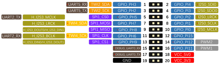
K2B Pinout
K2B has a 20Pin GPIO header.
Note
1. Functions marked with * or in red font are the default software configurations. To configure them for other functions, please modify pin mux in source code.
2. DEBUG_UART0_RX / TX are configured by default for serial debugging and are not recommended for use as ordinary serial ports or for other functions.
3. TWI means I2C: TWI1_SCK / TWI1_SDA are equivalent to I2C_CLK / I2C_SDA.

K2C Pinout
K2C has a 20Pin GPIO header.
Note
1. Functions marked with * in the image are the default software configurations. To configure them for other functions, please modify pin mux in source code.
2. DEBUG_UART0_RX / TX are configured by default for serial debugging and are not recommended for use as ordinary serial ports or for other functions.
3. TWI means I2C: TWI1_SCK/TWI1_SDA are equivalent to I2C_CLK/I2C_SDA.
GPIO
WiringKP Installation
1. Use the command to check if the WiringKP tool is installed in the system.
2. (Optional) If WiringKP is not installed in the system, download the wiringKP archive from the cloud disk, extract it, and place the executable and library files into the /usr/bin and /usr/lib directories, respectively.
WiringKP Operations
Tip
During the demonstration, the K2B development board is used as an example.
GPIO/PWM Command Usage Guide
gpio readall           // Get the status of all pins
gpio read <wPi>        // Read pin level
gpio mode <wPi> <mode> // Set pin working mode (current version supports setting out/int/up/down/pwm modes)
gpio write <wPi> <val> // Set pin output level

// PWM-related commands
gpio pwmr <wPi> <val>    // Set ARR
gpio pwm <wPi> <val>     // Set CCR
gpio pwmc <wPi> <val>    // Set prescaler coefficient
gpio pwmTone <wPi> <val> // Set frequency
Set PH5 to Output Mode, Output High Level
The PC pins output 1.8V, and the PH pins output 3.3V. After configuring the pins, you can use a multimeter to measure that the PH5 pin is at a high level.
kickpi@kickpi:~$ gpio mode 0 out
kickpi@kickpi:~$ gpio read 0
0
kickpi@kickpi:~$ gpio write 0 1
kickpi@kickpi:~$ gpio read 0
1
kickpi@kickpi:~$
Set PH5 to Input Mode
kickpi@kickpi:~$ gpio mode 0 in
kickpi@kickpi:~$ gpio mode 0 down
kickpi@kickpi:~$ gpio read 0
0
kickpi@kickpi:~$ // Short pins 3 and 4
kickpi@kickpi:~$ gpio read 0
1
kickpi@kickpi:~$
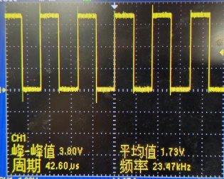
Set PH2 to PWM Mode
// By default, outputs a square wave with a frequency of 23475Hz and a 50% duty cycle
root@kickpi:~# gpio mode 3 pwm
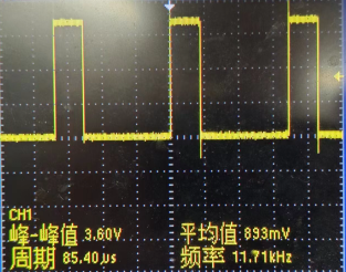
Adjust Duty Cycle
Note
PWM Duty Cycle = CCR/ARR
CCR range: 0~65535, default 512
ARR range: 1~65536, default 1024
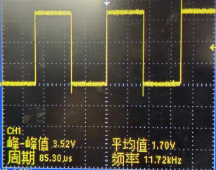
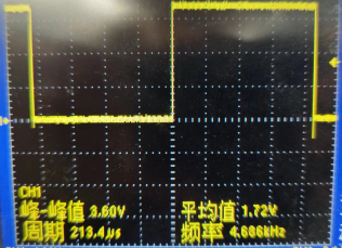
Adjust Frequency
// Default output frequency is 23475Hz
gpio mode 3 pwm
// Set prescaler coefficient to 5, output frequency = 23475/5 = 4695Hz, actual frequency is 4688Hz, error is negligible
gpio pwmc 3 5
gpio_para
gpio_para is located in the system directory /sys/class/gpio_sw and is the control driver for Allwinner GPIO, enabling simple high/low level control.
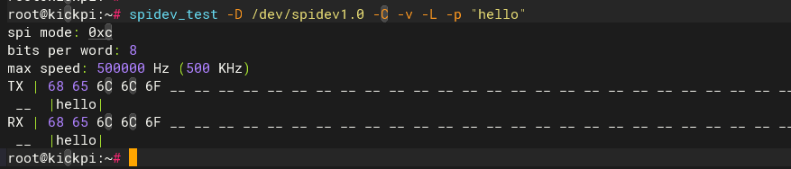
SPI
Tip
Short MISO and MOSI
Serial Port
Tool Preparation
- Hardware: USB to TTL cable
Note
Red: VCC (no need to connect); Green: TX; White: RX; Black: GND

TTL Ordinary Serial Port
Connect using a serial port tool.

Serial Port Settings
ttyAS5 is serial port 5, corresponding to pins PH2 and PH3, with a baud rate of 115200:
Send data to the serial port:
Receive data: