Quick Start
Kickpi K10B currently supports Android and Debian system.
To start using Kickpi K10B, you need to prepare the following items:
- Power Supply
- Display and Display Cable
- Boot Media
- Keyboard and Mouse
Note
If you want to use K10 as a headless device accessed via network, please refer to SSH Connection.
Tools Preparation
Power Supply
K10B supports 2 power modes.
| Power Mode | Voltage/Current |
|---|---|
| Type-C | 5V/2A (2A is the baseline, or above) |
| BAT | 3.8V-4.6V / 3A (Maximum charging current is 3A) |
Type-C
Warning
K10B supports Type-C power supply and BAT power supply. When using Type-C power supply, you must install the power switching terminal on the end of the expansion pin close to the screw hole (marked in the diagram)!

BAT
Warning
K10B supports Type-C power supply and BAT power supply. When using BAT power supply, you must install the power switching terminal on the end of the expansion pin away from the screw hole (marked in the diagram)!

Display
| Interface | Maximum Resolution Support |
|---|---|
| HDMI | 4096×2160@60Hz |
| MIPI | 2000x1200@120Hz |
| LVDS | 1280x800@60Hz |


Boot Media
K10B comes with eMMC (embedded Multi Media Card) on-board by default, and has Android operating system pre-installed. External boot media is not required. However, for subsequent use, if you want to change the operating system or sideload another OS from SD card, you need to prepare a SD card with ≥ 16GB storage capacity.

Keyboard and Mouse
Kickpi K10B has 1 USB 3.0 port and 1 USB 2.0 port. You can use any USB port to connect a keyboard or mouse.

Buttons
Kickpi K10B has 5 physical buttons on-board, each one has unique function, here are their usage description:
-
POWER: Power button.
-
RST: Short press to hot reset device once.
-
USER: System default configuration is volume up.
-
FEL: Used in the scenario of installing OS Image to on-board eMMC. When pressed and held with a power-on action, SoC's Init code will put device into MASKROM mode, cooperate with corresponding flashing tool to install Image into eMMC. MASKROM mode means cheating SoC init code into thinking eMMC has nothing programmed, even without U-boot or U-boot is corrupted and unable to work correctly. It gives people a chance to reprogram eMMC after bricking it.
-
TEST: System default configuration is volume down.


System Startup
User and Password
For any Linux distro Image we released, Default user and password for different distros are as follows:
| System | Username | Password |
|---|---|---|
| Debian | kickpi | kickpi |
| Debian | root | root |
Hardware Installation
In below installation diagram, we have installed the power supply, HDMI display, mouse, and keyboard to Kickpi K10B (If in your scenario, K10B works without display, here is a way to tell how the device's working and troubleshoot issues via on-board LED).
Note
FPC Antenna has bare metal surface, should avoid direct contact with board. Antenna may also generate electromagnetic interference, harm DDR's signals, please place antenna spatially away from DDR and SoC.

LED Status Indicator
You can tell the system working status via the LED indicators.
- K10B board has two LED indicators. green LED is the power indicator, and blue LED is the heartbeat indicator.
Success
Green LED is steady on, blue LED is blinking.
Failure
If green LED is off when device is powered on, please check power supply or short circuit issue. Green LED sucks current directly from DC power without any external control. If the blue LED is off or steady on (no blinking), kernel panic or died. Blinking is controlled by a kernel driver. All our released OS Image work this way: Android, Ubuntu, Debian, Armbian.
System Desktop
K10B supports Android operating system. When our released OS images are installed, you can tell which OS is installed by checking the desktop wallpaper.


WIFI/BT
The K10B development board supports operating systems such as Android, Debian, and Ubuntu. This section will introduce how to connect to Wi‑Fi and Bluetooth via the graphical interface in each of these different system environments.
Note
This section only provides a simple demonstration. For testing WiFi/Bluetooth/mobile networks via command line or other methods (only some boards support mobile networks), please refer to the network testing chapter in the functional testing section.
Pull down the notification bar on the desktop, turn on Bluetooth and Wi‑Fi, then long‑press to enter the connection interface.


Power On/Off
The KICKPI motherboard powers on automatically when connected to a power supply. While powered on, you can shut it down either physically or via software.
- Physical shutdown: Press and hold the Power button on the motherboard for 10 seconds(K7S_F requires external buttons), or unplug and replug the power cord (this method is not recommended as it may cause data loss or damage to the motherboard).
- Software shutdown: On the system desktop, locate the appropriate menu and select Shut Down.


Installing Operating System
Obtaining Image
Obtain Kickpi K10B image files from OneDrive.
Note
Image naming description: update-a733-kickpi-k10b-android-mipi0-multi-detect-2026050717.img
update: indicates full image package.
a733-kickpi-k10b: main control model is a733, hardware board type Kickpi K10B.
android: file system is Android.
mipi0-multi: K10B mipi0 interface display, compatible with multiple MIPI screens.
2026050717: image release date.
USB Installation
Tools Preparation
- Hardware: USB A to C burning cable.
- Software: Flashing tool PhoenixSuit V2.0.2, USB driver AW_Driver_V2.0.2, system Image.
USB Driver Installation
1. Connect the board to the host PC using a USB A to C cable. Navigate to the extracted AW_Driver_V2.0.2 directory, click and run InstallUSBDrv.bat to install the driver.

Driver installed successfully in Device Manager:

Installation Steps
1. Connect the board to the PC via USB A to C burning cable, put the board into installation mode, green LED is steady on.
Note
Installation mode:
When board is in power on state, connect to Windows PC, press and hold the FEL button (don't let loose), then short press the RST button once, the flashing tool will detect the device, then let loose the FEL button.
2. Open PhoenixSuit from the extracted PhoenixSuit V2.0.2 folder as Administrator.

3. In the flashing software, click the Firmware tab, click Image to select the Image to flash.

4. Put the board into installation mode again. Once the software detects the device, installation will start automatically, showing the following screen. Wait for the installation to complete.
Note
A733 board supports Upgrade for Android system installation. After waiting for "Device Connected" to appear in the bottom right corner, click the Upgrade button to upgrade.
Note
Installation mode:
When board is in power on state, connect to Windows PC, press and hold the FEL button (don't let loose), then short press the RST button once, the flashing tool will detect the device, then let loose the FEL button.

5. Image flashing completed, wait for the system to enter the desktop.
Success
Green LED is steady on, blue LED keeps blinking (blue LED will not light up immediately, please be patient).
After flashing, wait for the first boot to enter the desktop normally before powering off. Powering off in the middle may cause system abnormalities!

SD Card Installation
K10B has a SD card slot (microSD aka. TransFlash or TF) which can also serve as a bootable device. In K10B's boot sequence, SD card has higher priority, so K10B always tries to boot from SD card first, when no one mounted, K10B then boots from on-board eMMC. In this document, we use SD card, TF and SD means the same thing.
With tools, we can make 2 types of booting card. SD Boot Card works like a portable edition OS, e.g. Windows PE. We use SD Boot Card to power device for some maintain and fix purposes, also can be used to verify your own customization. The second type is SD installation card. You create this kind of booting card when you try to use it to install new Image into on-board eMMC. It contains a specific script to create partition, format FS, copy files to eMMC. Make sure you understand what you need and create the right SD card.
Tools Preparation
Note
SD Boot Card: Contains bootloader and complete system image, supports device booting directly from SD card, used in scenarios like built-in storage failure, development debugging.
SD Installation Card: Stores firmware image and installation script, used to install or upgrade firmware to the device's built-in storage (e.g., eMMC).
- Hardware: Windows PC/laptop, Power Adapter, SD Card, SD Card Reader.
- Software: Flashing tool PhoenixCard, system Image.
SD Boot Card
1. Navigate to the extracted PhoenixCard folder, launch PhoenixCard.

2. Follow the steps shown in the diagram to operate, install the downloaded image to the SD card.
Note
During the operation, PhoenixCard will request to format the SD card, just confirm the formatting.

3. SD Boot Card creation completed.

4. Power off the board, insert the SD Boot Card into the TF card slot, reconnect the power supply, wait patiently, and check if the desktop appears normally.
Success
Green LED is steady on, blue LED keeps blinking (blue LED will not light up immediately, please be patient).
SD Installation Card
1. Navigate to the extracted PhoenixCard folder, launch PhoenixCard.
2. Follow the steps shown in the diagram to operate, install the image to the SD card.
Note
During the operation, PhoenixCard will request to format the SD card, just confirm the formatting.

3. SD Installation Card creation completed.

4. Power off the board, insert the SD Installation Card into the TF card slot, power on again.
Success
The display will show an installation progress bar. When installation is complete, both green LED and blue LED will turn off. Power off the board, remove the SD card, power on the board again, wait for the system to reboot and enter the desktop.
System Configuration
In this chapter, you will use Mobaxterm for serial debugging, and ADB for Android system debugging.
Serial Debug
Using Serial Port debugging tool to connect K10B device to get a console. Please check pinout to find UART pins as shown in below diagram.
K10B DEBUG UART Pins
- 2D Pin Diagram

- Physical Image

Tool Preparation
- Software: Mobaxterm
- Hardware: Serial Debug Cable aka. USB-TTL debug cable
Note
Red: VCC (no need to connect); Green: TX; White: RX; Black: GND. If you can't get Serial Port output in Mobaxterm, just switch Green and White wire and try again.

Hardware Installation
- Diagram

Mobaxterm Configuration
1. Click session to create a new session window.
2. Select the session window type as serial.
3. Select the serial COM port number (Check COM number by opening Windows Device Manager -> Ports interface).
4. Set Speed(bps) to 115200.
5. Start the session window. As shown, after clicking OK, you will enter the command-line input window.

When the board is powered on and connected to the computer, Mobaxterm outputs boot information as follows.

Connection successful. Press Enter in the command-line interface to input commands, successfully logging into the mainboard console.

ADB
Android system supports ADB functionality. ADB (Android Debug Bridge) is an Android system debugging bridge tool. It supports connecting to devices via USB or network, enabling device management and debugging operations such as app installation, file transfer, command execution, etc.
Tool Preparation
- Hardware: USB Type-C Data Cable
- Software: download ADB_Tool
Hardware Installation
Connect one end of the USB TYPE-C data cable to the mainboard, the other end to the personal host.
Warning
The position of the power switching terminal needs to be changed according to the power supply method.
ADB Installation
1. Extract the compressed package, e.g., to Windows path D:\ADB\adb-tools.
2. Open cmd window, switch to the extraction directory.
3. Run the command. Successful run indicates installation success.

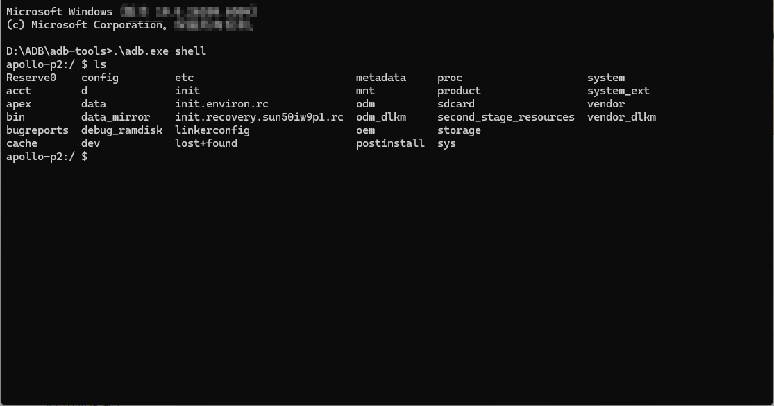
4. Start ADB debugging.
SSH
SSH stands for Secure Shell, an encrypted network transmission protocol. Its core function is to securely remotely log into servers, execute commands, or transfer files in insecure network environments.
Account and Password
Default usernames and passwords for different systems are as follows:
| System | Username | Password |
|---|---|---|
| Debian11 | kickpi | kickpi |
| Debian11 | root | root |
IP Address Acquisition
DHCP automatically assigns IP addresses; no settings are needed. Device IP can be obtained in multiple ways.
- Within the system: Connect the board to a display, log into the system, use
ifconfig eth0to get the IP address. - Via serial port: Enter
ifconfig eth0in the serial terminal to get the IP address (Serial connection refer to Mobaxterm section above).
SSH Connection
Enter the command in the command line to perform SSH connection:
Example:
PS C:\Users\16708> ssh kickpi@192.168.77.186
The authenticity of host '192.168.77.186 (192.168.77.186)' can't be established.
ED25519 key fingerprint is SHA256:635IZrLQdeYlWWl3SCdLxu9fxLEPmStBapj4APCjzZE.
This key is not known by any other names.
Are you sure you want to continue connecting (yes/no/[fingerprint])? yes
Warning: Permanently added '192.168.77.186' (ED25519) to the list of known hosts.
kickpi@192.168.77.186's password:
Welcome to Ubuntu 24.04.2 LTS (GNU/Linux 6.1.75 aarch64)

 * Documentation:  https://help.ubuntu.com
 * Management:     https://landscape.canonical.com
 * Support:        https://ubuntu.com/pro

This system has been minimized by removing packages and content that are
not required on a system that users do not log into.

To restore this content, you can run the 'unminimize' command.
To run a command as administrator (user "root"), use "sudo <command>".
See "man sudo_root" for details.

kickpi@kickpi:~$
Q&A
- ROOT User Login Failed?
1. Check if configuration was successful
Run the following commands. If the output is PermitRootLogin yes, it indicates configuration success:
console$ cat /etc/ssh/ssh_config | grep PermitRootLogin
PermitRootLogin yes
console$ cat /etc/ssh/sshd_config | grep PermitRootLogin
PermitRootLogin yes
2. Root user login configuration
Modify SSH configuration files: