UART
The Rockchip platform UART is based on the 16550A serial port standard. The expansion pin UART information is as follows:
| Mainboard | SOC | Platform | Expansion Pins |
|---|---|---|---|
| K1 | RK3568 | Rockchip | UART X4 |
| K1B | RK3568 | Rockchip | UART X2 |
| K3 | RK3562 | Rockchip | UART X3 |
| K7 | RK3576 | Rockchip | UART X5 |
| K7C | RK3576 | Rockchip | UART X4 |
| K8 | RK3588 | Rockchip | UART X5 |
| K11C | RK3566 | Rockchip | UART X3 |
The Allwinner platform UART is compatible with 16550 UARTs. The expansion pin UART information is as follows:
| Mainboard | SOC | Platform | Expansion Pins |
|---|---|---|---|
| K2B | H618 | Allwinner | UART X2 |
| K2C | H618 | Allwinner | UART X2 |
| K4B | T113 | Allwinner | UART X3 |
| K5C | A133 | Allwinner | UART X1 |
| K9 | T527 | Allwinner | UART X2 |
| K10B | A733 | Allwinner | UART X2 |
Related Terminology Introduction
| Term | Description |
|---|---|
| UART | Universal Asynchronous Receiver/Transmitter |
| Console | Console, the TTY device used for outputting debug information in the Linux kernel |
| TTY | TeleType/TeleTypewriters, originally referring to teletypewriters, now generally refers to terminal devices connected to computer serial ports. TTY devices also include virtual consoles, serial ports, and pseudo-terminal devices. |
| /dev/ttyS | Ordinary serial port device name |
| /dev/ttySA | Allwinner platform serial port name |
| /dev/ttyUSB | USB to serial port device |
Hardware Connection
UART communication requires a minimum of 3 wires to operate (full-duplex communication):
- TXD (Transmit Data): Data transmission end. The device sends data out through this line.
- RXD (Receive Data): Data reception end. The device receives external data through this line.
- GND (Ground): Ground wire, used to ensure a common voltage reference level between the two devices (common ground).
The UART between two devices requires cross-connecting RX and TX, directly connecting GND, and optionally directly connecting VCC.

DTS Configuration
Taking enabling UART device 0 as an example, add the following node in the dts:
Driver Path
Rockchip platform UART uses the 8250 serial driver:
drivers/tty/serial/8250/8250_core.c
drivers/tty/serial/8250/8250_dw.c
drivers/tty/serial/8250/8250_dma.c
drivers/tty/serial/8250/8250_port.c
drivers/tty/serial/8250/8250_early.c
Allwinner platform UART uses a dedicated serial driver:
longan/kernel/linux-4.9/drivers/tty/serial/sunxi-uart.c
longan/kernel/linux-4.9/drivers/tty/serial/serial_core.c
stty Test
Configure UART device 5, set input/output baud rate to 115200, 8 data bits:
Send data "kickpi" to UART device 5:
Capture data received by UART device 5:
Hardware Usage Example
Using the K7 mainboard as an example, this section explains how to connect the UART pins on the mainboard's expansion pins.
1. Check the mainboard expansion pin diagram and its corresponding physical location.
Note
The diagram shows that the K7 is equipped with five UART channels and one DEBUG UART. UART8 is located at pin 17 and pin 19.
DEBUG UART is only used for DEBUG debugging and not for other functions.

2. Check the expansion pin voltage diagram to determine that the power domain for UART8 is 1.8V.

3. Connect devices with the same power domain.
Warning
For UART connection, the TX and RX power domains must be consistent!
4. The UART8 power domain is 1.8V. Use the UART8 ports of two mainboards for connection: cross-connect RX and TX, and directly connect GND.

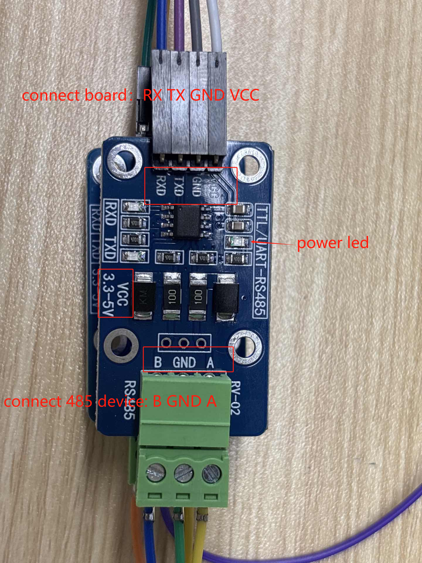
RS485 Conversion Module
RS485 communication uses the chip's UART. This chapter introduces the wiring for the UART-to-RS485 module (it is recommended to purchase this module from KICKPI official sources).
Wiring Method
The RS485 module VCC can be powered with 3.3V/5V.
Warning
The RS485 module can only be used with UART ports at 3.3V logic levels.
Note
The connection method for the 4PIN end to the development board UART port is as follows (corresponding top to bottom):
Motherboard: RX TX GND VCC
Module: RXD TXD GND VCC
The connection method for the 3PIN end to the RS485 device is as follows (corresponding top to bottom):
Module: A GND B
RS485 Device: A GND B
RS232 Conversion Module
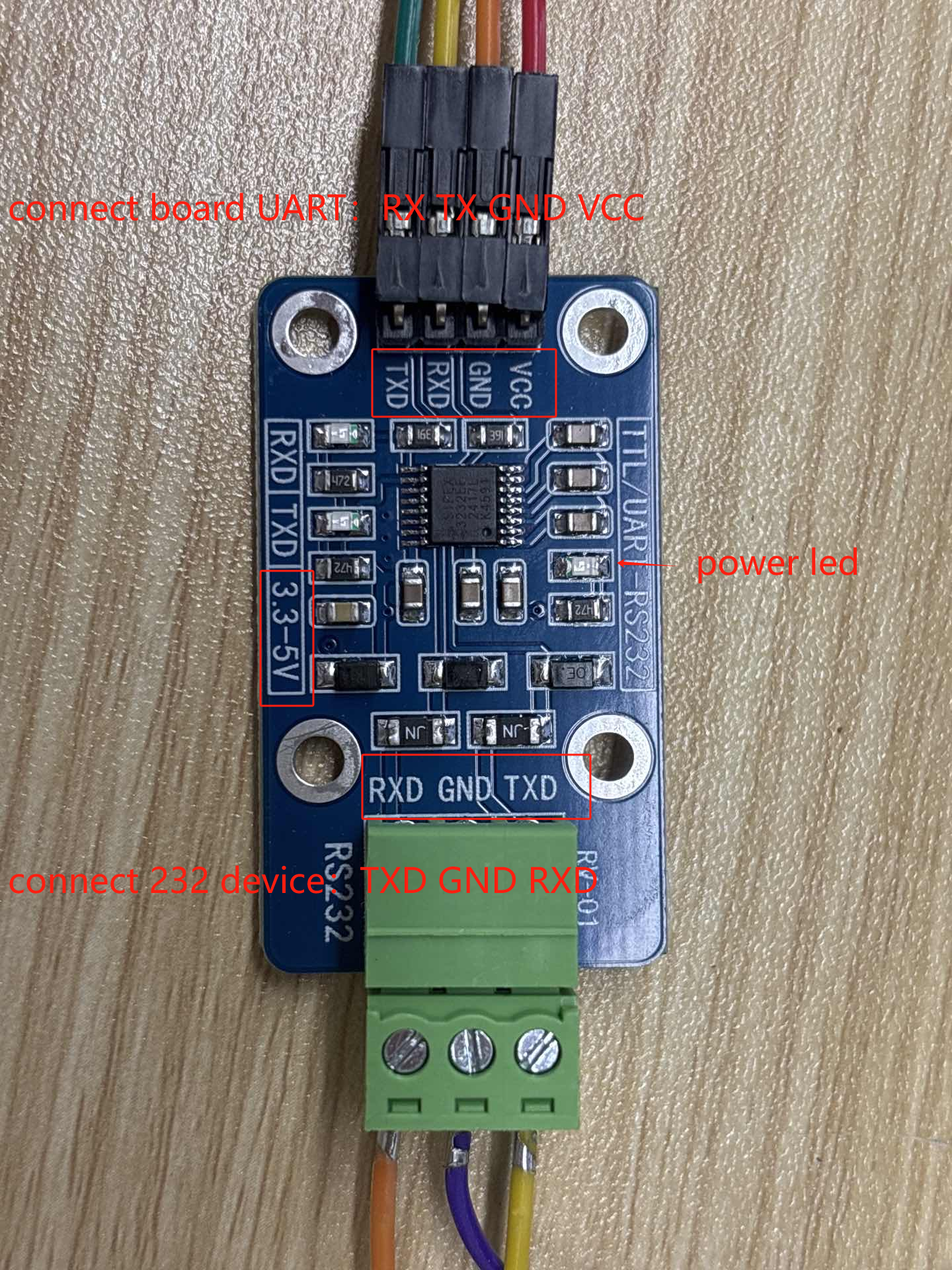
RS232 communication uses the chip's UART. This chapter introduces the wiring for the UART-to-RS232 module (it is recommended to purchase this module from KICKPI official sources).
Wiring Method
The RS232 module VCC can be powered with 3.3V/5V.
Warning
The RS232 module can only be used with UART ports at 3.3V logic levels.
Note
The connection method for the 4PIN end to the development board UART port is as follows (corresponding top to bottom):
Motherboard: TX RX GND VCC
Module: RXD TXD GND VCC
The connection method for the 3PIN end to the RS232 device is as follows (corresponding top to bottom):
Module: RXD GND TXD
RS232 Device: TXD GND RXD
USB to UART Adapter Adaptation
Since USB to UART adapters from different manufacturers have varying device IDs, the kernel does not include drivers for all models by default.
Adaptation Steps
1. Connect the USB to UART adapter and check the newly added USB PID and VID.
```
$ lsusb
Bus 003 Device 001: ID 1a86:7523
```
2. Add the corresponding device PID and VID to the kernel. Kernel paths for each chip are as follows:
| Chip                      | Kernel Path                                           |
| ------------------------- | ----------------------------------------------------- |
| A133                      | `kernel/linux-4.9/drivers/usb/serial/option.c`        |
| H618                      | `longan/kernel/linux-5.4/drivers/usb/serial/option.c` |
| T113                      | `kernel/linux-5.4/drivers/usb/serial/option.c`        |
| T527                      | `kernel/linux-5.15/drivers/usb/serial/option.c`       |
| RK356x (Linux 5.10)       | `kernel/drivers/usb/serial/option.c`                  |
| RK356x/RK3588 (Linux 6.1) | `kernel-6.1/drivers/usb/serial/option.c`              |
| RK3576 (Linux 6.1)        | `kernel/drivers/usb/serial/option.c`                  |

Taking RK356x Linux 5.10 as an example, open `kernel/drivers/usb/serial/option.c` and add the entry above the terminating entry at the end of `option_ids[]`.

!!! Note
    The procedure is exactly the same for other chips: locate `option.c` at the corresponding path from the table above, search for `/* Terminating entry */` to find the end of the array, and insert the new entry above it. The length of `option_ids[]` may vary across kernel versions, but the insertion position is always before the terminating entry.

```diff
--- a/kernel/drivers/usb/serial/option.c
+++ b/kernel/drivers/usb/serial/option.c
@@ -2210,6 +2210,7 @@ static const struct usb_device_id option_ids[] = {
         { USB_DEVICE_AND_INTERFACE_INFO(OPPO_VENDOR_ID, OPPO_PRODUCT_R11, 0xff, 0xff, 0x30) },
         { USB_DEVICE_AND_INTERFACE_INFO(SIERRA_VENDOR_ID, SIERRA_PRODUCT_EM9191, 0xff, 0xff, 0x30) },
         { USB_DEVICE_AND_INTERFACE_INFO(SIERRA_VENDOR_ID, SIERRA_PRODUCT_EM9191, 0xff, 0, 0) },
+        { USB_DEVICE(0x1a86, 0x7523) }, /* 1a86:7523 QinHeng Electronics HL-340 USB-serial adapter */
         { } /* Terminating entry */
};
```
3. Recompile the kernel and flash the system. After connecting the USB to UART adapter, use the newly created tty device for serial communication.
```
$ ls /dev/tty*
```